|
Music Studio |
|
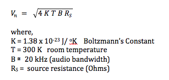
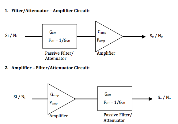
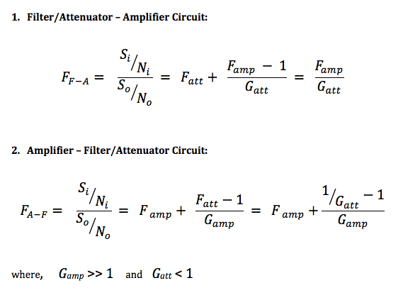
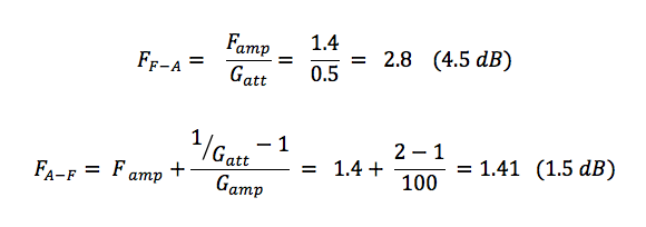
Before continuing the discussion of hooking up a sound source to the pre-amplifier of a mixer console or audio interface, I want to bring up the topic of noise – the unwanted sounds in our recordings. The description, analysis and mitigation of noise in electronic circuits are vast subjects covered in textbooks, research papers, and university engineering courses. I’ll just touch on the more pertinent information here. For an expert treatment on this subject, Henry Ott’s seminal monograph is probably the best source of information: Henry Ott, “Noise Reduction Techniques in Electronic Systems,” 2nd Ed., Wiley, 1988. There are many sources of noise that can inject a noise voltage into our circuit and ‘interfere’ with our desired signal voltage, giving us a degraded sound recording. These sources of noise can be categorized as being internal to the circuit and external to the circuit. Internal Sources: 1. Thermal Noise This noise originates from the random thermal motion of electrons in conducting materials, and produces a root-mean-square (rms) voltage This noise is primarily associated with resistors. For a source resistor RS = 150 Ohms, the thermal noise voltage is approximately Vn = 223 nV. 2. Shot Noise This noise originates from the discrete nature of electric charge and its emission across potential barriers in semiconductor devices like diodes and bipolar junction transistors. Although it is usually small compared to thermal noise, shot noise is a contributor to the noise added to a signal by amplifier circuits that contain many diodes and bipolar junction transistors. 3. Flicker or “1/f ” Noise This noise is a waveform whose power spectral density (PSD) goes down with increasing frequency f with a 1/f dependence -- this is characterized as “pink noise”. The origin of this noise in electronics is most likely due to the impurity traps and generation/recombination centers in semiconductor materials used for the diodes and transistors. External Sources: 1. Ambient Noise This is the background noise picked up by a microphone, if a microphone is being used. 2. Electromagnetic Interference The external electric and magnetic fields present in the space surrounding our circuit can be coupled to the metal wires in our circuit. In particular, the long wires of our audio cable can act as an antenna in receiving electromagnetic radiation. The result is ‘noise’ (unwanted) currents and voltages induced in our circuit. Sources of this electromagnetic interference range from the low-frequency (60 Hz) magnetic fields from AC power lines to the high-frequency electric fields of radio and microwave radiation. All of the noise sources described above create uncorrelated noise. When noise voltages are produced independently and there is no relationship between their instantaneous amplitudes or phases, they are said to be uncorrelated. Total noise power is then the sum of individual noise powers. Therefore, the resultant total noise voltage is the square root of the sum of the squares of the individual noise voltages. There is also noise categorized as correlated noise. Correlated noise voltages are related to the signal voltages, and are caused by nonlinear current-voltage relationships in active devices such as the transistors in amplifiers. Nonlinear amplification of signal voltages leads to the production of unwanted harmonic voltages (mixing of signals at the same frequency) and intermodulation voltages (mixing of signals at different frequencies). These two nonlinear effects are quantified by the amplifier specifications of Total Harmonic Distortion (%THD) and Intermodulation Distortion (usually specified by a quantity called the third-order intercept point IP3). The presence of noise from internal sources in our circuit is unavoidable – it’s just the physics of the motion of electrons in conducting and semi-conducting materials. But there are things we can do to try to control and mitigate noise through good circuit design practices. A good example of this is to get a low-noise amplifier into the signal path as soon as possible, especially if the sound source has a low signal-to-noise power ratio (S/N), such as with a microphone. To show this, consider these two alternative circuits: where, G and F are, respectively, the power gain (unitless) and noise factor (unitless) of the circuit blocks. The noise factor Famp is given by, and serves as a figure of merit for how much noise power Namp is added to the amplifier output by the electronics inside the amplifier. In the spec sheet for an audio amplifier, its noise performance is given by the Equivalent Input Noise Voltage EIN (V), which is related to noise factor F as, A low-noise amplifier has a noise factor F ~ 2, and with a source resistor RS = 150 Ohms, the corresponding equivalent input noise voltage per unit bandwidth (B = 1 Hz) would be For the circuits above, the overall noise factor for the cascade of the two circuit blocks together can be estimated from the Friis formula , The noise factor of an amplifier circuit depends on the types of active semiconductor devices used, as well as on the embedding impedances and operating conditions (bias currents) of the active devices. Although more costly, it is worthwhile to use a very-low-noise amplifier with high gain up front in a cascade of circuits, since the overall noise factor of the combined circuits will be dominated by the noise factor of this front-end amplifier. As an example, suppose we had the following: Amplifier: Famp= 1.4 Gamp = 100 (+20 dB power gain) Filter/Attenuator: Gatt = 0.5 (-3.0 dB power loss) Clearly, having the amplifier precede the filter/attenuator yields a 3 dB improvement in output S/N ratio. Keeping noise under control in each mixer channel is important because the noise power of each channel will sum together in the output bus. Mitigating the effect of external electromagnetic interference on the circuit will be the subject of my next post, as I look at the difference between unbalanced and balanced audio cables.
|
Categories
All
Archives
May 2023
|


 RSS Feed
