|
Music Studio |
|
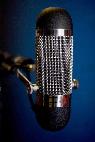
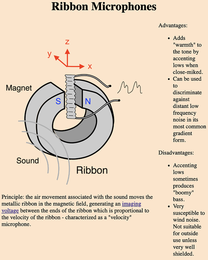
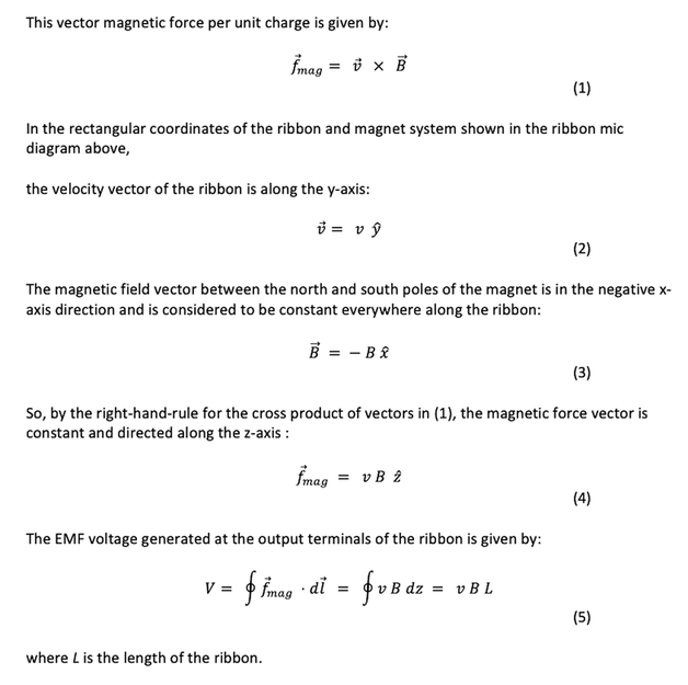
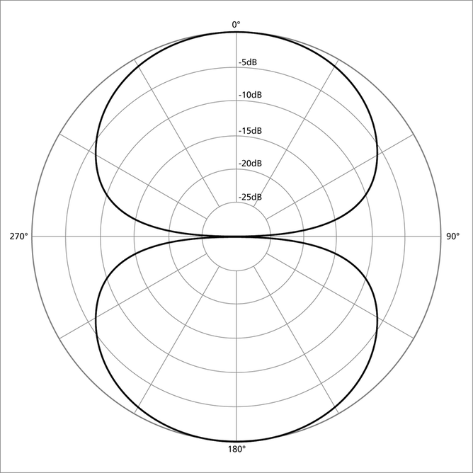
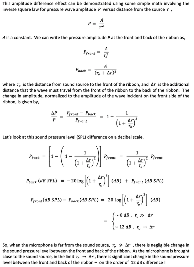
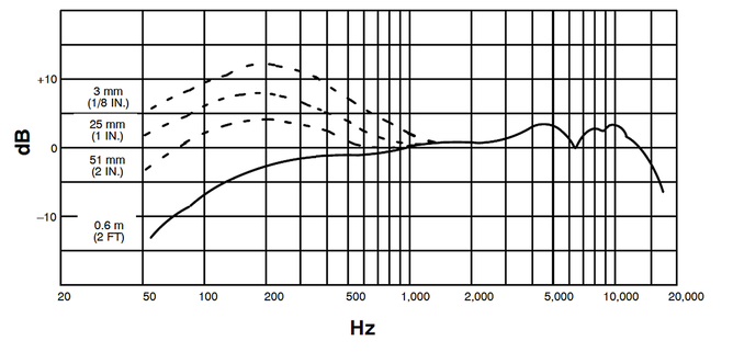
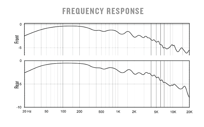
A microphone is a transducer, converting sound wave energy to electrical energy. The sound wave is a longitudinal pressure wave (compressions and rarefactions of the air molecules) that causes a thin diaphragm in the microphone to vibrate. As we discussed in the previous post on Dynamic Microphones , this vibrating diaphragm is attached to a metal wire coil that moves in the presence of a magnetic field, generating an electromotive force (EMF) voltage. There is a related type of “dynamic” microphone, called the Ribbon Microphone, where a thin, metallic diaphragm moves back and forth within a permanent magnetic field, also generating an EMF voltage. The microphone (mic) shown in the photo at the top of this post is an Audio Engineering Associates (AEA) R84 ribbon mic. The AEA R84 ribbon mic is a popular choice of many studio engineers for its warm and rich sound, reminiscent of the classic RCA ribbon mics of the 1930s. The “inner workings” of a ribbon mic are shown in the figure below. Sound pressure waves strike a thin, corrugated aluminum ribbon, usually from both the front and back sides. The thickness of this ribbon is only 2 microns (micrometers), and its dimensions are on the order of 5 mm width x 60 mm length. The difference in pressure between front and back (pressure gradient) causes the ribbon to move inward and outward from its rest position. The very thin, lightweight ribbon can react swiftly and accurately to the incoming soundwave pressure differential. The ribbon moves with velocity at right angles to the magnetic field lines between the magnet poles. The mobile charge carriers in the metallic sheet feel a force, the Lorentz magnetic force, creating an EMF voltage across the terminals of the ribbon. This voltage is the source of the electrical signal in the microphone output circuit. Let’s look more closely at the EMF voltage generated by this moving metallic ribbon. The Lorentz magnetic force acts on the mobile charge carriers in the metallic ribbon. The differential pressure of the sound wave causes the ribbon to vibrate about its rest position. Consequently, the ribbon moves with positive and negative velocities, and the generated voltage in (5) is proportional to the velocity. This voltage waveform therefore “images” the pressure variations of the input sound wave and constitutes the output signal of the microphone. The important characteristics of a microphone include: 1.Polar response pattern 2.Frequency response 3.Output signal level 4.Output resistance (impedance) Ribbon mics usually have a “bi-directional” polar response pattern, as shown here: Ribbon microphones, by the nature of their design, are pressure-gradient microphones. Both the front and rear of the ribbon are exposed equally to sound pressure variations. With sound waves approaching from the front of the mic, there is a phase shift and amplitude change between the pressure waves that are incident on the front and back of the ribbon itself. The difference in sound pressure between the two sides causes the ribbon to move, and a mic signal is generated. The same thing happens when sound waves approach from the rear of the mic. But when sound waves approach the mic from the sides, there will be equal pressures on the front and back of the ribbon. Therefore, there is no motion of the ribbon and no output signal generated. With this bi-directional ( “figure-8” ) pattern, the mic picks up sound well in both forward- and reverse-looking directions while rejecting sound from its sides. This pattern can be used to good effect, such as in making a stereo microphone pair (the Blumlein technique). The directionality property of this microphone leads to a very interesting frequency response characteristic, called the proximity effect . This effect is discussed next. Proximity Effect The proximity effect is the increase in low-end frequency response in a pressure gradient microphone as the microphone is brought closer to the sound source. The pressure difference between the front and back of the ribbon causes it to move. This difference is created mainly by the phase and amplitude changes of the sound wave as it propagates from the front of the mic to the back (and vice versa). The soundwave phase shift is frequency dependent, with the pressure gradient sensitivity increasing at a rate of approximately 6 dB per octave. To compensate for this increasing sensitivity, the ribbon mounting structure is damped to “flatten” the microphone frequency response, i.e., the damping causes a sensitivity decrease of roughly 6 dB per octave. On the other hand, soundwave amplitude change is NOT frequency dependent. The amplitude decrease of an outwardly propagating sound wave generated by a point source is given by an inverse square law with distance traveled. As the distance between the sound source and the microphone gets smaller, the amplitude difference of the pressure wave between the front and back of the ribbon becomes larger. With the ribbon mic positioned close to the sound source, the pressure difference across the ribbon at the low and low-mid frequencies is dominated by wave amplitude changes. This “boost” in the bass frequencies is called the proximity effect . At mid and higher frequencies, the wave phase-change effect on pressure gradient is rapidly increasing with frequency ( approx. 6 dB/octave) and takes over as the dominant factor in pressure gradient. ( Recall that in order to keep the frequency response somewhat “flat” as frequency increases, there is damping of the response by the ribbon mount structure at a rate of roughly -6 dB/octave.) The frequency response curve for the Shure BETA 57A pressure-gradient microphone shows very nicely the “bass boost” from the proximity effect. Microphone placements range from a large distance from source (2 ft.) to a very short distance from source ( 1/8 inch). The frequency response curve for the AEA R84 ribbon microphone is shown below. It is not stipulated in the specifications sheet what the distance is between sound source and the ribbon microphone in this frequency response graph. The proximity effect with its low-end boost gives this ribbon microphone its desired rich, warm, even dark characteristic that is well suited for voice and solo instruments. By close mic’ing the instrument, the low-end can be effectively added to a thin mix. As usual, caution must be exercised to avoid a muddy low-end in the mix, so use proper mic positioning for recording. You don't want to have to "fix in the mix" with EQ , a practice very much frowned upon ! Finally, here are some notes on the output signal level and impedance of a ribbon mic . Because the EMF voltage generated by the ribbon is much less than that generated by the coil in a dynamic mic, a “step-up” transformer is typically used on the output. This transformer boosts the output voltage level, but unfortunately also increases the output resistance. (The transformer also prevents phantom power (48 VDC) from being accidentally applied across the ribbon, which could destroy the ribbon.) The spec sheet for the AEA R84 ribbon mic lists an output voltage (sensitivity) of 2.5 mV per Pascal of pressure into an unloaded circuit, and an output impedance of 270 Ohms. Due to the low output voltage level and relatively high, frequency-dependent output impedance, ribbon mics are often used with their own specially designed pre-amps. A high-impedance, high-gain ribbon-specific preamp will really bring out the charm and character of a passive ribbon microphone. In the next post, we’ll take a look at the studio workhorse microphone – the condenser mic. |
Categories
All
Archives
May 2023
|
 RSS Feed
