|
Music Studio |
|
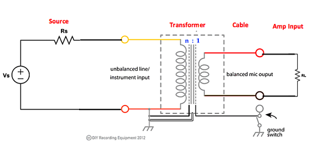
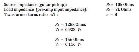
OK, the technical talk continues – another post in our series of connecting a sound source to the input of a pre-amplifier in a mixer console or audio interface. The goal all along has been to get a good portion of the signal voltage generated in the source transferred to the input of the pre-amplifier, and to do so without introducing too much noise into the system and without distorting the signal waveform. We’ve seen that it is desirable to have low source impedance and high load impedance due to the voltage divider effect of the circuit. Along with low source impedance, it is desirable to have a cable with as little parasitic capacitance as possible so that there is little high-frequency distortion of the signal waveform due to the low-pass filtering effect of the cable. So, cable lengths should be as short as practical. Additionally, a balanced cable with a grounded shield can have less capacitance per unit length between the positive and negative wires than an unbalanced cable. Lastly, to keep noise to a low level, particularly in long cable runs from source to load, we need to use a three-wire balanced audio cable with a properly grounded shield and a low-noise (low EIN voltage) differential-input pre-amplifier. The microphone input impedance of a modern pre-amp is typically on the order of 2k – 10k Ohms. The source impedance of a good microphone is on the order of 150 Ohms (with some vintage, and still very popular, models such as the Shure SM57 being about 600 Ohms). These microphones typically have an XLR connector, making them suitable to attach directly to a balanced audio cable that goes to the XLR connector on the mixer console or audio interface. In contrast, electric guitars and piezo pickups on acoustic guitars have source impedances that are relatively high, in the range 5k – 20k Ohms. Furthermore, output connections from these instruments are typically ¼" TS jacks, meant for attaching unbalanced instrument cables. This is a “double whammy” – high source impedance and an unbalanced instrument cable. Often, there is a Line/Instrument input ( ¼" TS jack) on the mixer or audio interface that has a built-in pad (voltage attenuator) that boosts the input impedance up to 10k – 20k Ohms. This higher input impedance presents a high enough impedance to the guitar instrument so that the pickup circuit is properly loaded, i.e., does not have to source more current than it is capable of providing. So connecting directly to this Line/Instrument input is acceptable, as long as the instrument cable length remains short ! But in practice, there is usually a long distance between instrument and the sound board. What to do ? The magic box – the Direct Inject (DI) box – comes to the rescue ! The DI box can accomplish the following tasks: 1. Present a high-impedance load ( > 100k Ohms) to the instrument source, so that it is properly loaded. 2. Provide a low-impedance, balanced output suitable for attaching a balanced cable to run all the way to the mixer console microphone XLR input connection. 3. Electrically isolate the source circuit from the load circuit. The two circuits are magnetically coupled, and each can have its own ground. The primary electrical component in a DI box is a transformer – two wire coils that share time-varying magnetic field flux (no direct-current connection). The ratio of the number of loops (turns) of the primary coil (the one on the left) and the secondary coil (the one on the right) is n : 1, where n > 1 is an integer. The impedance R1 looking into the primary coil is what the source “sees” as the load impedance, and the voltage V1 across the primary coil, which is referenced to the local chassis ground, is given by, The current I1 flowing into the primary coil is very small, since R1 is large. The impedance R2 looking into the secondary coil is what the load “sees” as the source impedance, which is now effectively a low-impedance source, as we desire. The voltage V2 across the secondary coil (which is the same as the voltage VL across the load) is given by, This signal voltage V2 = VL is maintained between the positive and negative wires inside the balanced cable and is symmetrically centered around ground potential (0V). The outer shield of the cable is grounded at the far end of the cable at the pre-amplifier circuit. Let’s put some example values into these equations to see how the DI box transforms impedances. The transformer presents the desired high-impedance (128k Ohms) load to the unbalanced instrument source, while also providing an effective low-impedance (156 Ohms) source connected to the pre-amp microphone input via a fully balanced cable.
A note on signal voltage levels is warranted here. The voltage delivered to the pre-amp input with the transformer in the circuit is, from above, VL = 0.116 VS , which is significantly reduced from the value VS (-18.7 dB). This occurs because the transformer is configured to transform impedances to the proper levels, and with its primary-to-secondary turns ratio of 8:1, the voltage is actually “stepped down”. In most cases this is not a problem, because instrument output levels range from tens of millivolts all the way up to a couple of volts (line level output from electronic keyboards). So the reduced voltage level is now commensurate with microphone voltage levels and, hence, is suitable for connecting to the microphone input of the pre-amplifier at the mixer board. A last word regarding the DI box – about the “ground lift” switch. The source circuit and cable/load circuit are electrically isolated from each other. They are coupled via the time-varying magnetic field flux passing through both primary and secondary windings of the transformer. The source circuit is shown tied to its own local chassis ground (which may be connected to another ground through the shield of the unbalanced instrument cable). The balanced cable shield is grounded at the pre-amplifier circuit. If the chassis ground is isolated from earth ground at the DI box, then connecting the DI box chassis to the earth ground of the balanced cable shield should be OK, as there is a single-point connection to earth ground. However, if the DI box chassis is connected to its local earth ground (e.g., via a connection to the output jack of an electronic keyboard), then there would exist a two-point connection to earth grounds that have slightly different electric potentials. This forms a ground loop circuit carrying noise currents that can create a noticeable ‘hum’ or ‘buzz’ in the sound. To avoid this situation, the ground lift switch is opened and the ground loop circuit is broken. |
Categories
All
Archives
May 2023
|


 RSS Feed
