|
Music Studio |
|
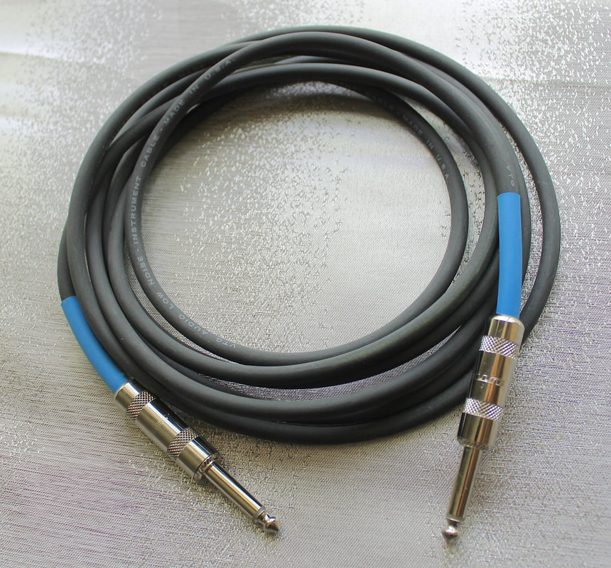
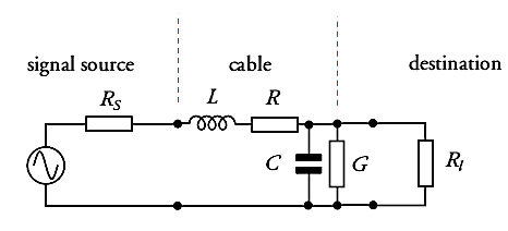
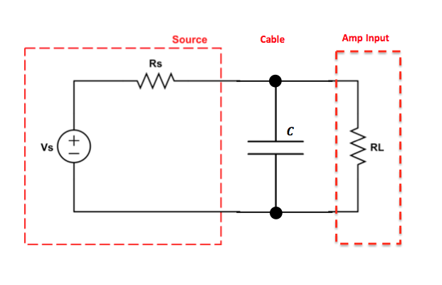
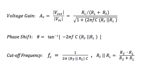
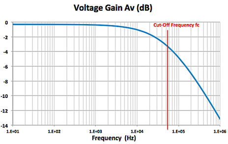
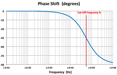
Now we’re ready to connect our sound source (microphone, pickup, instrument output) to the next ‘building block’ in our chain of signal processing, usually a mixer console or audio interface unit. To do this, we ‘transmit’ our audio signal through a cable connected between the sender and receiver. This sounds like a very mundane task. But there is definitely an art and science to this, which warrants taking a closer look at cables and connectors. There are many blogs and videos on this topic -- not all saying the same thing ! For the next few posts, I’ll put on my electrical engineering hat to add my two cents to the mix using electronic circuit theory. Cable Equivalent CircuitCables used for transmitting signals consist of long lengths of metal wires in either a two-conductor or a three-conductor wire configuration. These wires are part of the full electrical circuit that starts with the source electronics and ends with the receiver electronics. The cable is modeled by the circuit elements in the figure below , The circuit elements are not lumped components but are distributed quantities ‘spread’ along the long lengths of the metal conductor system. The inductance per meter L’ models the effect of the time-changing current in the wire (changing magnetic flux), and the capacitance per meter C’ models the effect of the time-changing potential difference (voltage) between the metal conductors (changing electric field). The resistance per meter R’ models the small resistive loss (Joule heating) due to the metal’s finite conductivity, and the conductance per meter G’ models the small polarization loss of the dielectric material that separates the conductors. When the signal voltage varies at very high frequencies (radio frequencies f > 100 MHz), the cable acts as a transmission line, guiding the voltage waves down its length. The wavelength λ of the voltage wave is given by λ= v/f where v and f are, respectively, the speed and frequency of the wave. The speed of an electromagnetic wave in a coaxial cable filled with dielectric material is about 2/3 the speed of light, or ~ 2 x 10^8 m/s. For frequency f = 1 GHz, the wavelength λ = 0.2 m ≈ 8 inches. So the wave nature of the transmission line would have to be accounted for in a circuit analysis when interconnects are longer than a couple of inches. Voltage and current waves travel forward and backward on this transmission line, reflecting at its terminations where there is an impedance mismatch. There exists a characteristic impedance (Zc ) for this high-frequency transmission line given by the ratio of the amplitude of the forward-propagating voltage wave (V+) to the amplitude of the forward-propagating current wave (I+), where L' and C' are, respectively, the distributed inductance and capacitance of the transmission line. L' and C' are determined by the configuration and geometry of the cable and by the dielectric material properties of the cable. Cables are designed to have standardized characteristic impedances -- 75 Ohm (coax) and 300 Ohm (twin-lead) cables for UHF/VHF applications, and 50 Ohm (coax) cables for radio-frequency and microwave circuit applications. Please note that if you look at a cable, you won’t see a 75 Ohm, 300 Ohm or 50 Ohm resistor anywhere !! The characteristic impedance Zc has units of Ohms since it is defined as the ratio of voltage amplitude to current amplitude in the wave propagating down the transmission line. It is a useful quantity in the analysis of high-frequency circuits. At audio frequencies, the wavelength λ > 10,000 m, which is about 6.2 miles !! SO …. in the equivalent circuit model for an audio frequency cable, we really can consider the distributed circuit elements of the transmission line to be simply lumped components. Furthermore, the inductive reactance (2π f L), metal resistive loss (R) and dielectric loss (G) are quite small in audio cables, so these elements will be neglected here. The primary feature of the audio cable is its capacitive loading effect on the circuit. This loading effect increases with frequency and with cable length. In essence, the audio cable is nothing more than wires connecting together two circuits – just like the wires you use on a breadboard to build electronic circuits. But the wires of the audio cable do present a sizeable parasitic capacitance in the circuit. The capacitive loading on the circuit creates a low-pass RC filter. The source resistor RS is the Thevenin equivalent output impedance of the signal source circuit. The load resistor RL is the input impedance looking into the input of the next stage (usually an amplifier circuit). The amplitude and phase changes of the output sinusoidal voltages Vout = VRL from the input sinusoidal voltages Vin = VS are calculated using AC circuit analysis. At frequencies well below the cut-off frequency fc , the amplitude of Vout is given by the voltage divider expression, Also, for frequencies well below fc , there is only very small phase shift of the sinusoidal voltage from input to output , The audio signal is a voltage signal that is processed through electronic circuits from the sound source to the analog-to-digital (A/D) converter, and from the digital-to-analog (D/A) converter to the power amplifier driving the monitor speakers. As the signal is passed from one electronic circuit to the next, we need to pay attention to this voltage divider action. The Thevenin equivalent circuit of the sound source is comprised of the voltage source VS and the output resistance Rout = RS . The input of the next circuit, such as the pre-amp in the mixer board or audio interface box, is comprised of its input resistance Rin = RL, i.e., the input resistance of the second circuit is the load resistance of the first circuit. Therefore, to maintain signal strength (voltage amplitude), we can see from the voltage divider equation above that we desire to have a sound source with a low output resistance (low impedance or Lo-Z ) and a pre-amp with a high input resistance (high impedance or Hi-Z). And this is exactly what is done in sound gear. Impedance levels are roughly categorized as follows: Complex time-domain voltage signals will contain high-frequency components. As the frequencies of these components approach the cut-off frequency of the audio cable's low-pass filter, say above ~ fc /10 , the amplitude and phase shift of each component will be altered. This means that the time-domain voltage waveform at the load will not be an exact duplicate of the waveform at the source -- this is DISTORTION of the signal ! As an example, a 100-ft. long audio cable may have a capacitance on the order of C = 2 nF. The source (microphone) has a low output resistance RS = 150 Ohm, and the mixer pre-amp has a relatively high input resistance RL = 4k Ohm. This gives a cut-off frequency A sound waveform with fundamental frequency of 10 kHz may have harmonics at and above 50 kHz that will be affected by the low-pass filtering of the cable. It may be, however, that the distortion created in the time-domain signal waveform in this example is inaudible to humans. If an audio cable with capacitance C = 20 nF had been used in the above example, the cut-off frequency would be fc ≅ 55 kHz and distortion of the sound would be significant and quite audible. We should always be mindful of keeping source resistance and cable capacitance to low values. In my next post, I’ll take a look at noise in our audio circuits and ways to control it, including the use of balanced audio cables, impedance transformers (DI boxes) and ground shields.
Comments are closed.
|
Categories
All
Archives
May 2023
|




 RSS Feed
