|
Music Studio |
|
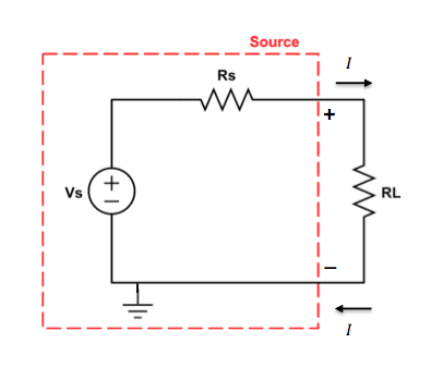
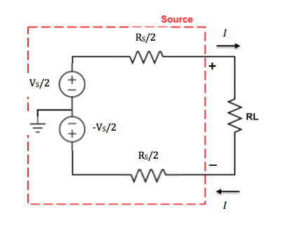
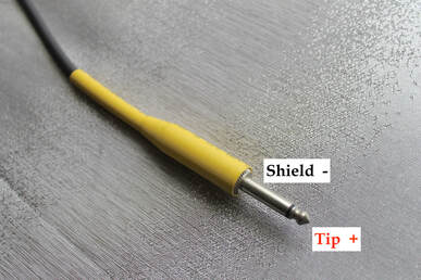
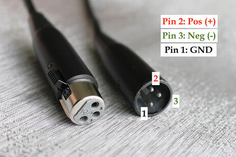
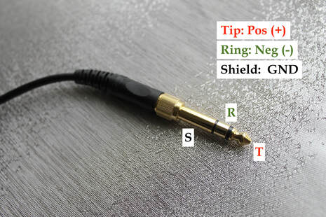
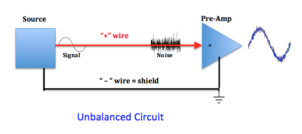
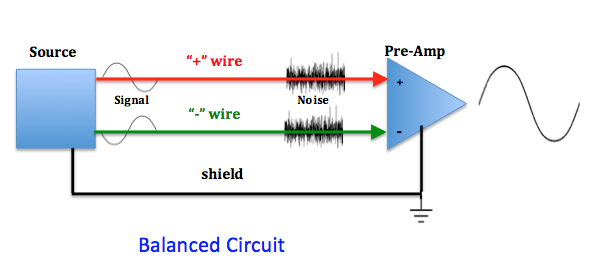
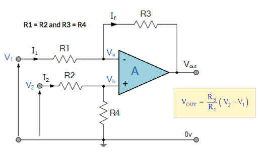
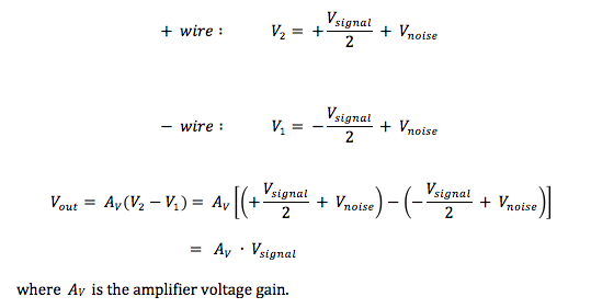
In this post, I return to the subject of audio cables and hooking up the output of a sound source to the pre-amplifier of a mixer console or audio interface. The electrical circuit consisting of the sound source, the audio cable and the load (the input of the pre-amp) is shown in its most simple form in the following figure. The Thevenin equivalent circuit for the sound source consists of a time-varying voltage VS(t) and an output resistance RS (or more generally, an output impedance ZS = RS + jXS, where the reactance XS originates from capacitance and inductance in the source). The audio cable is simply the two metal conductors connecting the positive (+) terminal ( or “red wire”) and the negative (-) terminal ( or “black wire”) of the source to the load. A high conductivity metal wire at low frequencies is a surface of constant potential, so the potential difference (voltage) between the two wires remains the same all the way down the cable from source to load. Of course, this voltage along the cable is varying with time – it is the signal voltage VSIGNAL(t). The load resistance RL is the equivalent input resistance of the pre-amp (again, more generally, an input impedance ZL = RL + jXL). In the circuit above, the negative lead (black wire) is shown connected to an earth ground. This is done to give a reference potential (0 V) to a point in the circuit, so that the potentials in the circuit are not “floating” . Grounding the circuit is a good safety practice for AC-powered electronic circuits, and as we will see, is also useful in providing some noise immunity. The point at which the circuit is grounded is entirely arbitrary, but is commonly done on the negative lead wire at the source. It should be noted that we are focused on voltages in an audio circuit – our information signal is a voltage that is ‘processed’ through a chain of circuits, like voltage amplifiers, filters and transformers. Voltage doesn’t “flow” in a circuit – it is simply the potential difference between two points in the circuit. We don’t usually focus on the low-level current I(t) that does flow in the circuit, but it is there. In fact, the word “circuit” means a closed loop path, without which we would not have a functioning electrical system. The same current I shown leaving the positive terminal of the source in the figure above returns to the source via the negative terminal. Even though the negative wire may be grounded, this wire is a necessary part of the signal path. [ In a future post, I’ll talk about the circuit formed by the power amp – speaker cable – speaker (monitor). Here, both voltage and current need to be considered, as what is desired is to get the maximum power transferred from amp to speaker.] It was mentioned above that the placement of the ground in the circuit is arbitrary. In the circuit below, a different choice is made for the location of the ground. But the operation of this circuit is absolutely identical to that of the original circuit above . The load resistor can’t “tell” the difference ! But these two circuits are key to understanding the difference between an unbalanced audio cable and a balanced one. A two-wire cable connected to the positive (+) and negative (-) terminals of the source in the first circuit configuration above is said to be “unbalanced”, since the signal voltage is maintained on the positive wire with respect to the grounded negative wire. The connectors used on the ends of this two-wire unbalanced audio cable are typically ¼-inch TS (Tip-Shield) plugs. The Tip is connected to the insulated positive wire that runs inside the cable. The Shield is connected to the grounded negative wire that is a metal braided mesh or foil surrounding the insulated inner wire. A three-wire cable connected to the positive (+), negative (-), and ground terminals of the source in the second circuit configuration above is said to be “balanced”, since the signal voltage is maintained between the positive and negative wires and is symmetrically centered around ground potential (0 V). The connectors used on the ends of this three-wire balanced audio cable are typically XLR 3-pin male plugs and female jacks. Pins 2 and 3 in the XLR shell are connected to the insulated positive and negative wires, respectively. Pin 1 of the XLR is connected to the outer metal shield conductor surrounding the insulated inner wires. A balanced cable can also be terminated with a ¼-inch TRS (Tip-Ring-Shield) connector. (It should be pointed out that a 3-wire cable with ¼-inch TRS connectors is also frequently used as a stereo two-channel (left and right) unbalanced cable, such as your headphone cable.) At this point, please note that unbalanced and balanced audio cables should NOT be called high impedance (Hi-Z) and low impedance (Lo-Z) cables, respectively. These cables are NOT high-frequency wave-guiding transmission lines that have a characteristic impedance ZC. These cables are just wires that connect sources to loads, and it is the source and load that are described by high and low impedances. It has become common practice to associate XLR balanced cables with microphones that are low-impedance sources – hence the erroneous attribution of low impedance to the XLR balanced cable. Similarly, it is common practice to associate ¼” TS unbalanced cables with guitar pick-ups that are high-impedance sources – hence the erroneous attribution of high impedance to the ¼“ TS unbalanced cable. The use of balanced audio cables becomes necessary when you have a low-voltage (low S/N) source, such as a microphone, that needs to be connected to a pre-amp that is a long distance away. In such cases, the mitigation of noise induced on the wires from external electromagnetic interference is critical. The outer grounded metal conductor is partially effective in shielding the inner wires from electromagnetic interference. However, currents induced in the outer conductor from electric fields can penetrate through the braid and around the connectors to the interior of the cable, and low-frequency magnetic fields penetrate the shield easily. In an unbalanced cable, the noise voltage created on the positive wire is added to the signal voltage, and both are amplified in the single-ended pre-amp, as shown below. In a balanced cable, noise voltage (with respect to ground potential) is induced equally on the co-located positive and negative wires. By using a differential input amplifier, however, the common-mode noise voltages can be suppressed, as shown below. In practical differential-input amplifier circuits, the transistor devices are not perfectly matched and there are imbalances in bias currents. So there isn’t perfect cancellation of the common-mode noise voltages. Nonetheless, there is significant suppression of noise, and the use of balanced audio cables with differential-input amplifiers is well worth the effort. Next time, we’ll take a look at how to transform an unbalanced circuit into a balanced one – the role of the Direct Inject box.
|
Categories
All
Archives
May 2023
|
 RSS Feed
