|
Music Studio |
|
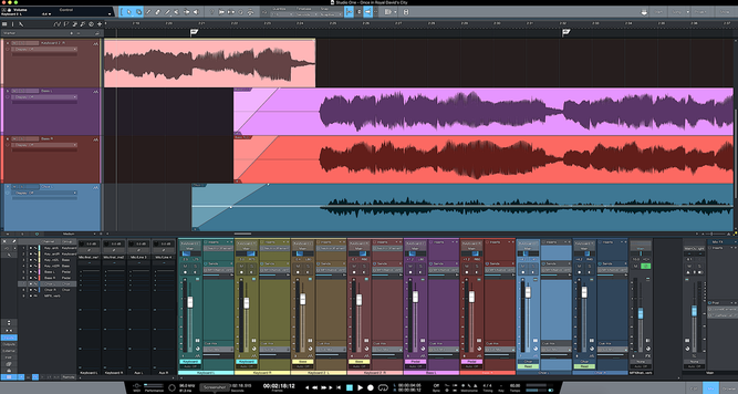
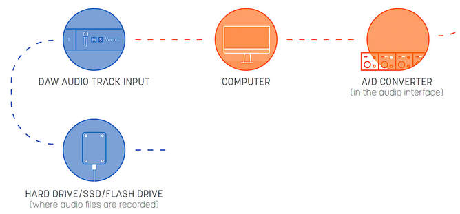
In the very first post of this blog back in April 2020, I drew up a block diagram of the basic elements of a home music recording studio. Without question, the heart of the system is the computer application called the Digital Audio Workstation (DAW). This digital audio workstation is essentially the home studio’s software version of the mixer console – that large desk of electronic hardware, sometimes called a sound board – found in professional music recording studios. So, it is no surprise that the GUI of the DAW looks just like a real mixer console. You can see the DAW interface in the screen capture above, with its channel strips, controls, meters, faders, etc. There are many well-known DAW applications, ranging from ‘free’ applications like Apple GarageBand that come packaged with your computer to expensive applications like Avid Pro Tools that are used in professional studios. In a previous post, I introduced the DAW that I use in my home studio – the PreSonus Studio One. For the next few posts, I will outline the basic ‘work flow’ of the DAW, starting in this post with the DAW input section used for the recording process. The signal flow in the DAW is important to understand in order to utilize the software properly. Unlike hardware components where you can visualize the signal flow in a system by the cables connecting the parts, signal flow in the software programming is not readily apparent to the user. Fortunately, simple block diagrams of the signal flow in a DAW are available for download from iZotope . The signal flow chart for the DAW input section used for recording is shown below. In the computer, the digital audio signal enters the DAW audio channel input section, where input gain can be trimmed and a phase shift can be applied. The phase Φ switch is used to shift the voltage waveform phase by 180 degrees. This has the effect of inverting the voltage waveform. This is done if two channels (say from two mics on the same sound source) have voltage waveforms that nearly cancel each other when mixed (added) together. So, engaging the 180-degree phase shift on one of these channels will mostly “fix” this waveform cancellation problem. It should be noted that the primary adjustment for recording level is usually done back at the analog pre-amplifiers in the Audio Interface Unit. But the level of the digital signal can be trimmed using the input gain control at this point. Setting the appropriate input level for recording was reviewed in the prior post Digital Signal Levels. The audio digital waveforms are then recorded to the external solid-state drive (SSD). The SSD is the “final” destination of the signal in the recording process. Clip Gain An extremely useful editing feature available in most professional DAWs is the clip gain adjustment tool. A custom drawn gain envelope modifies the amplitude level of the stored digital audio waveforms during playback. This process is “non destructive”, in that the recorded (stored) digital waveforms are not altered. The gain envelope can be drawn with as much detail as desired and applied over an entire clip (event) or down to individual notes. It can also be used to surgically remove an undesired sound from a track, although this is probably better accomplished using an audio repair tool specifically meant for doing this, such as the iZotope RX 8 plug-in. In the following example, the gain envelope is used to increase the dynamic contrast between two musical phrases. In the next few posts, we’ll take a look at the various kinds of signal processing done in the DAW to produce a final “mix-down” of the music.
Comments are closed.
|
Categories
All
Archives
May 2023
|


 RSS Feed
